Hardware documentation
AM2H modules are connected by standard 8 pin RJ45 network cables. Every AM2H ESP Wifi modul could be connected to selected sensors depending on the software configuration.
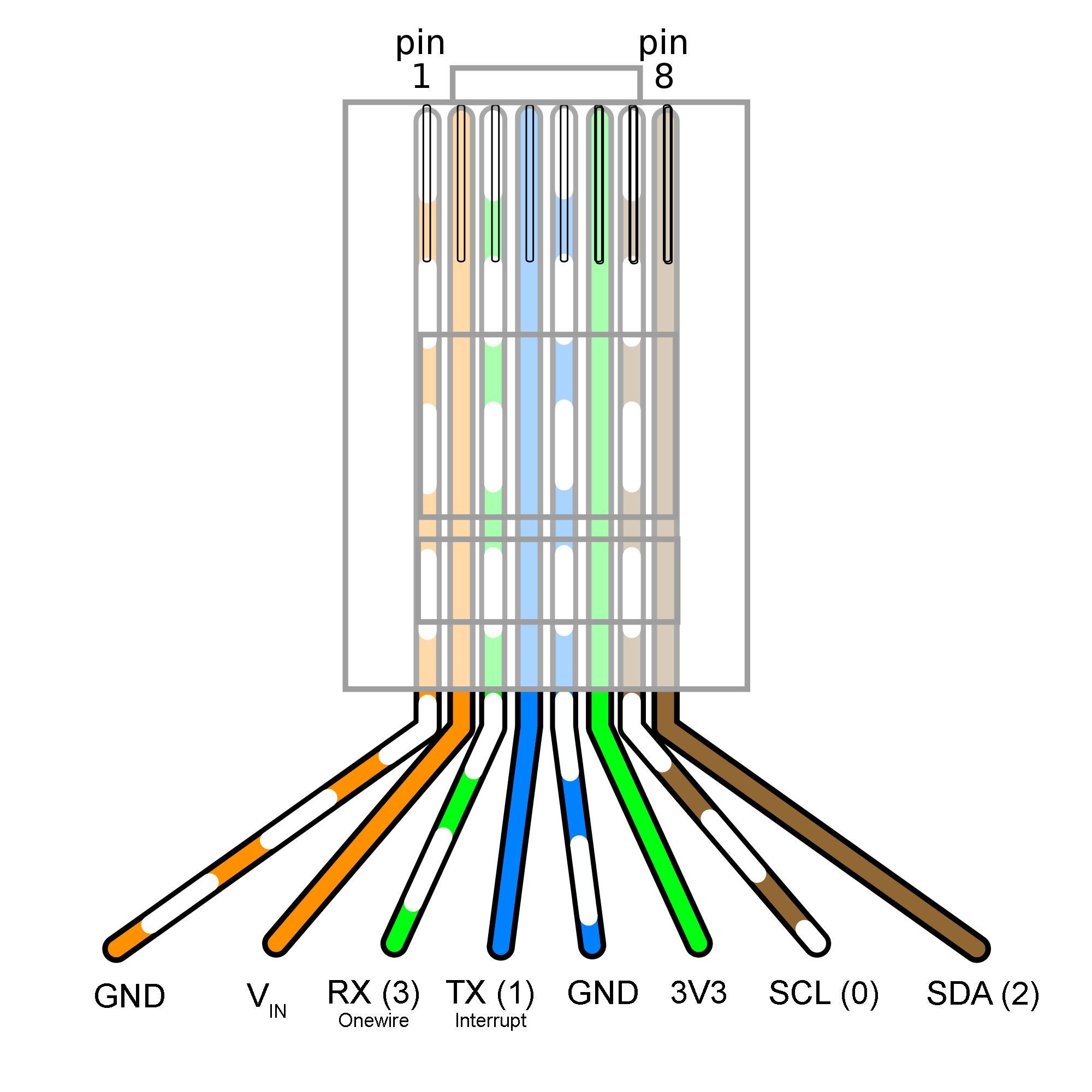
RJ45 Pinout
| PIN number | Name | Description |
|---|---|---|
| 1 | GND | Power Supply |
| 2 | VIN | Power Supply |
| 3 | RX | Onwire Data |
| 4 | TX | Interrupt |
| 5 | GND | Power Supply |
| 6 | 3V3 | Power Supply |
| 7 | SCL (0) | I2C Serial Clock |
| 8 | SDA (2) | I2C Serial Data |
Power supply Pin 1 and 2
AM2H modules are equipped with an AMS1117 3.3V voltage regulator. Limitations for the line regulation are within the range of 1.5V ≤ (VIN - VOUT) ≤ 12 V. The dropout voltage is around 1.5 Volt, it is recommended to power the module with 5 Volt. Power supply provides no additional protection circuit.
DS18B20 1-Wire® Temperature Sensor Pin 3
DS18B20 1-Wire® Temperature sensors are manufactured by Dallas Semiconductor Corp. The 1-Wire® Interface requires only one digital pin for two way communication with a microcontroller. The sensor can be powered with a 3V to 5.5V power supply and consumes around 1mA during active temperature conversions. An external 4.7k pull-up resistor between the signal and power supply is required to keep the data transfer stable.
Interrupt based pulse counter Pin 4
The module allows to counting pulses with an interrupt on Pin 4 which is set as internal pull-up. An external pull-up resistor is not required. The interrupt is set to trigger on the event of FALLING or LOW levels with a debounce time of 500 ms.
Regulated Power Supply PIN 5 and 6
Output of the voltage regulator is 3.3 V. Depending on the input power supply the AMS1117 voltage regulator could deliver up to 800 mA of power. For further information please refer to the technical datasheet.
I²C - Two Wire Interface Pin 7 and 8 (Pin 4 for external interrupt )
I2C or I²C is short for Inter-Integrated Circuit, a synchronous serial communication protocol developed by Phillips for communication between a fast Microcontroller and relatively slow peripherals (like Memory or Sensors) using just two wires. It is also known as TWI (Two Wire Interface). The I2C Bus consists of two wires called the Serial Data (SDA) and the Serial Clock (SCL). Data is transmitted through the SDA line while the SCL line is used to synchronize the devices with the clock signal. An external 4.7k pull-up resistor for both bus lines (SDA and SCL) are required. In case a Pcf8574 module is installed Pin 4 is used as an interrupt pin for the input signals. A combined usage with the puls counter is not possible.
RJ45 Connector layout "bottom" (tap down)
Flashing the device
AM2H devices could by flashed using a UART (USB to TTL converter) programmer. It is recommended to power the device with 5V using Pin 1 and 2 of the RJ45 connector. Connect the AM2H device to the FTDI adapter as shown in the table. To enable flash mode press flash button on the back of the device before connecting to the power supply and keep pressed until the device is connected to the power supply.
| PIN number RJ45 | Description | PIN FTDI |
|---|---|---|
| 1 - GND | Power Supply | GND |
| 2 - VIN | Power Supply | VCC |
| 3 - RX | Serial Rx | TX |
| 4 - TX | Serial Tx | RX |
AM2H_Core documentation
REST API
all HTTP/GET
configuration
  GET: api/v1/set?deviceId=myDevice9.123456789.123456789.12&ssid=ssid56789.123456789.123456789.12&pw=pw3456789.123456789.123456789.12&mqttServer=server-mh.fritz.box.123456789.123456789.123456789.&mqttPort=1883&ns=ns345678
  GET:  api/v1/restart  -> rebooting device
information
  GET:  api/v1/get        -> {
                              "deviceId":"myDevice9.123456789.123456789.12",
                              "ssid":"ssid56789.123456789.123456789.12", "pw":"...",
                              "mqttServer":"server-mh.fritz.box.123456789.123456789.123456789.",
                              "mqttPort":1883,
                              "ns":"ns345678"
                            }
  GET:  api/v1/status   -> {"statuslog":"[...logger content...]"}
MQTT configuration
All MQTT must be send retained except the set topics. Topics are not case sensitive.
##namespace##/config/##deviceNumber##/##plugin##/##00..19##/##topic##
Core config
all retained
akm/config/d_100/-/core/sampleRate => 15 (Sample rate in seconds)
akm/config/d_100/-/core/i2cMuxAddr => 0x70 (Mux adress only needed if i2cMux is installed)
akm/config/d_100/-/core/nickname => Ventilation (Nickname not mandadory)
Icounter
all retained
akm/config/d_100/0/Icounter/absCnt => e.g. 112345
akm/config/d_100/0/Icounter/unitsPerTick => e.g. 1
akm/config/d_100/0/Icounter/exponentPerTick  => e.g. 0   (10^X)
akm/config/d_100/0/Icounter/unitsPerMs => e.g. 1
akm/config/d_100/0/Icounter/exponentPerMs  => e.g. 0   (10^X)
akm/config/d_100/0/Icounter/zeroLimit  => e.g. 100
akm/config/d_100/0/Icounter/loc  => e.g. gasMeter      (location of the sensor for mqtt publish)
Example for gas meter:
zeroLimit = 300 => after 300 s without any impulse the power will be set zero
unitsPerMs = 360 => power equivalent per ms
exponentPerMs = 0 => exponent to above
unitsPerTick = 1 => volume equivalent per impulse
exponentPerTick = -2 => exponent to above
Bme680 configuration
all retained
akm/config/d_100/0/Bme680/addr => 0x77 / 0x0277
akm/config/d_100/0/Bme680/loc => firstFloor
akm/config/d_100/0/Bme680/offsetTemp => 0 // in 0.1 °C
akm/config/d_100/0/Bme680/offsetHumidity => 0 // in 0.1 % rH
akm/config/d_100/0/Bme680/offsetPressure => 0 // in 0.1 hPa

akm/storage/d_100/0/Bme680/setIAQ => 0 // only first time
error codes:
    BSEC_OK = 0,                                    /*!< Function execution successful */
    BSEC_E_DOSTEPS_INVALIDINPUT = -1,               /*!< Input (physical) sensor id passed to bsec_do_steps() is not in the valid range or not valid for requested virtual sensor */
    BSEC_E_DOSTEPS_VALUELIMITS = -2,                /*!< Value of input (physical) sensor signal passed to bsec_do_steps() is not in the valid range */
    BSEC_E_DOSTEPS_DUPLICATEINPUT = -6,             /*!< Duplicate input (physical) sensor ids passed as input to bsec_do_steps() */
    BSEC_I_DOSTEPS_NOOUTPUTSRETURNABLE = 2,         /*!< No memory allocated to hold return values from bsec_do_steps(), i.e., n_outputs == 0 */
    BSEC_W_DOSTEPS_EXCESSOUTPUTS = 3,               /*!< Not enough memory allocated to hold return values from bsec_do_steps(), i.e., n_outputs < maximum number of requested output (virtual) sensors */
    BSEC_W_DOSTEPS_TSINTRADIFFOUTOFRANGE = 4,       /*!< Duplicate timestamps passed to bsec_do_steps() */
    BSEC_E_SU_WRONGDATARATE = -10,                  /*!< The sample_rate of the requested output (virtual) sensor passed to bsec_update_subscription() is zero */
    BSEC_E_SU_SAMPLERATELIMITS = -12,               /*!< The sample_rate of the requested output (virtual) sensor passed to bsec_update_subscription() does not match with the sampling rate allowed for that sensor */
    BSEC_E_SU_DUPLICATEGATE = -13,                  /*!< Duplicate output (virtual) sensor ids requested through bsec_update_subscription() */
    BSEC_E_SU_INVALIDSAMPLERATE = -14,              /*!< The sample_rate of the requested output (virtual) sensor passed to bsec_update_subscription() does not fall within the global minimum and maximum sampling rates  */
    BSEC_E_SU_GATECOUNTEXCEEDSARRAY = -15,          /*!< Not enough memory allocated to hold returned input (physical) sensor data from bsec_update_subscription(), i.e., n_required_sensor_settings < #BSEC_MAX_PHYSICAL_SENSOR */
    BSEC_E_SU_SAMPLINTVLINTEGERMULT = -16,          /*!< The sample_rate of the requested output (virtual) sensor passed to bsec_update_subscription() is not correct */
    BSEC_E_SU_MULTGASSAMPLINTVL = -17,              /*!< The sample_rate of the requested output (virtual), which requires the gas sensor, is not equal to the sample_rate that the gas sensor is being operated */
    BSEC_E_SU_HIGHHEATERONDURATION = -18,           /*!< The duration of one measurement is longer than the requested sampling interval */
    BSEC_W_SU_UNKNOWNOUTPUTGATE = 10,               /*!< Output (virtual) sensor id passed to bsec_update_subscription() is not in the valid range; e.g., n_requested_virtual_sensors > actual number of output (virtual) sensors requested */
    BSEC_W_SU_MODINNOULP = 11,                      /*!< ULP plus can not be requested in non-ulp mode */ /*MOD_ONLY*/
    BSEC_I_SU_SUBSCRIBEDOUTPUTGATES = 12,           /*!< No output (virtual) sensor data were requested via bsec_update_subscription() */
    BSEC_E_PARSE_SECTIONEXCEEDSWORKBUFFER = -32,    /*!< n_work_buffer_size passed to bsec_set_[configuration/state]() not sufficient */
    BSEC_E_CONFIG_FAIL = -33,                       /*!< Configuration failed */
    BSEC_E_CONFIG_VERSIONMISMATCH = -34,            /*!< Version encoded in serialized_[settings/state] passed to bsec_set_[configuration/state]() does not match with current version */
    BSEC_E_CONFIG_FEATUREMISMATCH = -35,            /*!< Enabled features encoded in serialized_[settings/state] passed to bsec_set_[configuration/state]() does not match with current library implementation */
    BSEC_E_CONFIG_CRCMISMATCH = -36,                /*!< serialized_[settings/state] passed to bsec_set_[configuration/state]() is corrupted */
    BSEC_E_CONFIG_EMPTY = -37,                      /*!< n_serialized_[settings/state] passed to bsec_set_[configuration/state]() is to short to be valid */
    BSEC_E_CONFIG_INSUFFICIENTWORKBUFFER = -38,     /*!< Provided work_buffer is not large enough to hold the desired string */
    BSEC_E_CONFIG_INVALIDSTRINGSIZE = -40,          /*!< String size encoded in configuration/state strings passed to bsec_set_[configuration/state]() does not match with the actual string size n_serialized_[settings/state] passed to these functions */
    BSEC_E_CONFIG_INSUFFICIENTBUFFER = -41,         /*!< String buffer insufficient to hold serialized data from BSEC library */
    BSEC_E_SET_INVALIDCHANNELIDENTIFIER = -100,     /*!< Internal error code, size of work buffer in setConfig must be set to BSEC_MAX_WORKBUFFER_SIZE */
    BSEC_E_SET_INVALIDLENGTH = -104,                /*!< Internal error code */
    BSEC_W_SC_CALL_TIMING_VIOLATION = 100,          /*!< Difference between actual and defined sampling intervals of bsec_sensor_control() greater than allowed */
    BSEC_W_SC_MODEXCEEDULPTIMELIMIT = 101,          /*!< ULP plus is not allowed because an ULP measurement just took or will take place */ /*MOD_ONLY*/
    BSEC_W_SC_MODINSUFFICIENTWAITTIME = 102         /*!< ULP plus is not allowed because not sufficient time passed since last ULP plus */ /*MOD_ONLY*/
Bh1750 / (BH1721) configuration
all retained
akm/config/d_100/1/Bh1750/addr => 0x23 / 0x0423
akm/config/d_100/1/Bh1750/loc => firstFloor
akm/config/d_100/1/Bh1750/sensitivityAdjust => 0 // for Bh1721 always 0, for Bh1750 31..254 - standard 69
Rgbled configuration
all retained
akm/config/d_100/2/Rgbled/addr => 0x41 / 0x0341
akm/config/d_100/2/Rgbled/loc => firstFloor
akm/config/d_100/2/Rgbled/timeOn => 1000 // in ms
akm/config/d_100/2/Rgbled/timeOff => 1000 // in ms
akm/config/d_100/2/Rgbled/colorOn => RED // one of [WHITE, FUCHSIA, AQUA, BLUE, YELLOW, RED, GREEN, BLACK]
akm/config/d_100/2/Rgbled/colorOff => RED // one of [WHITE, FUCHSIA, AQUA, BLUE, YELLOW, RED, GREEN, BLACK]
akm/config/d_100/2/Rgbled/active => TRUE or >0 / FALSE or 0
akm/config/d_100/2/Rgbled/setState => ... // same as akm/firstFloor/signal/state + &active=TRUE/FALSE
Ds18b20 configuration
all retained
akm/config/d_100/3/Ds18b20/addr => 28ffd059051603cc
akm/config/d_100/3/Ds18b20/loc => firstFloor
akm/config/d_100/3/Ds18b20/offsetTemp => 0 // in 0.1 °C
Pcf8574 configuration
all retained
akm/config/d_100/0/Pcf8574/addr => 0x20 / 0x0120
akm/config/d_100/0/Pcf8574/loc => office
akm/config/d_100/0/Pcf8574/ioMask => [0..255] [1 = output, 0 = input]
akm/config/d_100/0/Pcf8574/reg => [0..255] [startup register state 0=GND, 1 = VCC]
akm/config/d_100/0/Pcf8574/onPort[0..7]Falling => akm/config/d_106/0/Pcf8574/setPort>port=4&state=0 [send MQTT payload onPort number 0..7 falling]
akm/config/d_100/0/Pcf8574/onPort[0..7]Rising => akm/config/d_106/0/Pcf8574/setState>reg=11111111 [send MQTT payload onPort number 0..7 rising]
set payload not retained
akm/config/d_100/0/Pcf8574/setPort => port=[0..7]&state=[0..1] [set state of port to 0=GND, 1 = VCC]
akm/config/d_100/0/Pcf8574/setState => ioMask=[0..255]®=[0..255] [set ioMask (optional) and/or reg (optional) to specific values 0=GND, 1 = VCC]
The ioMask defines the direction of the I/O ports. If the port is used as an output set the mask to 1. If the port is used as an input set the mask to 0. Payload in DEC number.
Port          7 6 5 4 3 2 1 0
Direction     I I I I I I O O
Mask          0 0 0 0 0 0 1 1
Payload for mask: 3 DEC
The startup register defines the port status after startup and can be used to set the port status for all ports at the same time. In case pull-up resistors are used for the input and/or output ports are active on ground the startup mask should be set to 1 [VCC] for the ports.
Port          7 6 5 4 3 2 1 0
Pull-up       1 1 1 1 1 1 1 1
Register      1 1 1 1 1 1 1 1
Payload for register: 255 DEC